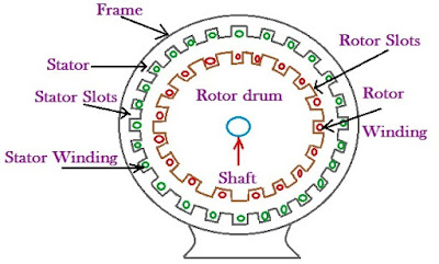
Construction:-
An induction motor consists of two main parts
- Stator
- Rotor
The stationary frame is called stator and the rotating armature is called rotor. The stator of induction motor is similar to that of the synchronous motor or generator. It is made of large number of stampings. These stampings are slotted in order to receive the stator windings. Figure below shows the construction of Induction motor.
 |
| Induction Motor |
The functions of various parts is as follows:-
- Frame:- Its function is to provide mechanical support to the entire construction. The frame also contains the stator winding of Induction motor.
- Air gap:- Air gap provides the space for the rotating magnetic field between the stator and rotor.
- Fan:- The fan rotates with the rotor. Its function is to cool down the motor.
- Slip rings:- The rotor winding terminals are permanently connected to the slip rings(in slip ring type induction motor). The slip rings are continuously in contact with the brushes which are pressed against slip rings. External connections from the brushes are brought out,
Figure below shows the rotor and stator of induction motor.
 |
| Stator and Rotor construction of Induction motor |
Rotor drum is provided with slots. The stator is stationary which can be star connected or delta connected to the 3Φ AC supply through a switch as shown in figure below.
 |
| Stator winding connections |
The function of stator winding is to produce a rotating magnetic field in the air gap between the stator and rotor. It should be known that the rotor is connected to any external supply. The current flows through the rotor due to principle of induction.
Working:-
The 3Φ induction motor has 3Φ winding which is supplied by 3Φ alternating voltage and 3Φ balanced current flow in the winding. The current produce magnetic flux which is constant in magnitude and rotating at synchronous speed. The rotating magnetic filed swift pass the rotor conductors which as yet are stationary. The relative velocity between the magnetic flux and stationary rotor conductors induces emf in the rotor conductors according to Faraday's Law of Electromagnetic Induction. The induced emf is directly proportional to the relative velocity between the magnetic flux and stationary rotor conductors. The frequency of induced emf is same as the supply frequency and the direction of induced emf is given by Fleming's Right Hand Rule.
Since the rotor conductor forms a closed circuit, rotor current produces which opposes the very cause producing it according to Lenz's Law. In this case, the cause which is producing the rotor current is relative velocity between the magnetic flux and stationary rotor conductors. Hence the rotor starts running in the same direction as rotating magnetic field and always try to catch up the the speed of rotating magnetic field.


0 comments: