Wednesday, September 2, 2015

Block Diagram Algebra

The transfer function for the input output behaviour of a linear system or element of a linear system is given by
G(s) = C(s)/R(s)
where R(S )-Laplace transform  of the input variable  and 
C(S)-Laplace transform of  the  output variable 

A control system may have many number of components  connected to each  other  and each components have its own transfer function .To show this different transfer function of each component a block diagram is generally referred .
block diagram of  a system is pictorial representation or convenient graphical representation of the input -output behaviour i.e. transfer function of each component and of the flow signals . The block diagram depicts the interrelationship  between different system components .The block diagram  representation is more advantageous than mathematical representation as it identical the flow of signal of the actual system more realistically .
The block itself shows transfer function and it is a system of mathematical  operation on the input signal to the block that produces output signal .The flow  of information is unidirectional from input to the output with the output being equal to the result of product of input and output transfer function. The blocks are connected by lines with arrows indicating the unidirectional flow of information. The arrowhead which points toward the block designates the input and the arrowhead coming out of the block that is leading away from the block represents the output. Such arrows are referred to as signal.
Block Diagram Algebra - Figure

The above figure shows that the signal into the block represents the input R(s) and the signal leading away from the block represents the output C(s), while the block itself represents the transfer function.
Summing Point - Figure
Summing Point

Summing Point :- The figure (b) shows the summing operation. The plus indicated that the signal a and b are to be added. The quantities being added have the same dimension and units. Figure (a) shows the differencing operation. The plus and minus sign indicates that the two signals a and b are to be subtracted. If the circle with cross symbol is not shown with any sign convention, by default the two signals are added.
Branch Point :- It is a point from which the signal from block goes concurrently to other block.

Wednesday, August 5, 2015

Control System - Some Important Definitions

Control System - Some Important Definitions
Photo Credit - www.semrush.com

Mathematical Models

Mathematical models may assume different forms. Depending on the particular system and the particular circumstances, one mathematical model may be better suited than other other models, Once a mathematical model of a system is obtained, various analytical and computer tools can be used for analysis and synthesis purpose.

Simplicity vs Accuracy

In obtaining a mathematical model, one must make compromise between the simplicity of the system and the accuracy  of the result of the analysis. In deriving a reasonably simplified model, it is necessary to ignore certain inherent physical properties of the system.
While solving a new problem, it is desirable to build a simplified model so that a general feeling for the solution should be felt as we feel when we have found solution to a very complex mathematical problem. A more complete model then can be built and used for a more accurate analysis. A linear lumped parameter model which may be valid in low frequency operations may not be valid at sufficiently high frequency. Since the neglected property of distributed parameters may become an important factor in the dynamic behaviour of the system.  

Linear System

A system is called linear if the principle of superposition applies. The principle of superposition states that the response produced by the simultaneous application of two different forcing functions is the sum of the two individual response. For the linear system, the response of several inputs can be calculated by treating one input at a time and adding the results. It is this principle that allows one to build up complicated solutions to the linear differential equation from simple solutions. In an experimental investigation of a dynamic system, if cause and effect are proportional thus implying that the principle of superposition holds then the system can be considered linear.

Linear Time Invariant System

A differential equation is linear if the coefficients are constants or functions only of the independent variables. Dynamic systems that are composed of linear time invariant lumped parameter components may be described linear time invariant (constant coefficient) differential equations. Such systems are called linear time invariant system. 
Systems that are represented by differential equation and coefficients are functions of time  then it is called as linear time varying system.

Controlled variable and manipulated variable

The controlled variable is the quantity or condition that is measured and controlled
The manipulated variable is the quantity or condition that is varied by the controlled variable so as to affect the value of the controlled variable.
Normally controlled output is the output of system.
Control means measuring the value of the controlled variable of the system and applying the manipulated variable to the system to correct or limit the deviation of the measured value from a desired value.

Plant

A plant may be a piece of equipment perhaps just a set of machine parts functioning together to perform a particular operation/task.

Processes

The process is defined in various ways depending on the context for which it is used. The Merriam Webster dictionary defines a process to be
a natural, progressively continuing operation or development marked by a series of gradual changes that succeed one another in relatively fixed way and lead toward a particular end or result. It may also be defined as an artificial or voluntary, progressively continuing operation that consists of a series of controlled actions or movements systematically directed toward a particular result or end.
Example :- chemical process, biological process.

System

A system is a combination of components that act together and perform a certain objective. A system is not limited to physical ones. The concept of the system can be applied to abstract, dynamic phenomena such as those encountered in economics.

Disturbances

A disturbance is a signal that tends to adversely affect the value of the output of a system. If disturbances is generate within the system, it is called internal while an external disturbance is generated outside the system and is an input.

Feedback Control

Feedback control refers to an operation that, in the presence of disturbance tends to reduce the difference between the output of a system and some reference input and does so on the basis of this difference.

Thursday, July 30, 2015

Transfer Function

Control System - Transfer Function
Photo Credit - techdissected.com

The transfer function of a linear time invariant differential equation system is defined to be the ratio of the Laplace transform of the output variable (response function) to the Laplace transform of the input variable (driving function) under the assumption that all the initial condition are zero.
Consider the linear time invariant system defined by the following differential equation:
A0yn + A1yn-1 + A2yn-2 +....................+ Any = B0xm + B1xm-1 + B2xm-2 +......................+ Bmx
Here n is greater than or equal to m.
Where y is the system’s output and x is the input. As we know that transfer function is the Laplace transform of the output response to the Laplace transform of input variable when all initial conditions are zero.
Transfer Function G(s) =
Y(s)
/X(s) = B0xm + B1xm-1 + B2xm-2 +......................+ Bmx / A0yn + A1yn-1 + A2yn-2 +....................+ Any

By using the concept of transfer function, it is possible to represent system dynamics by algebraic equations in s. If the highest power of s in the denominator is equal to n, the system is called an nth order system.
"When the transfer function of a physical system is determined, the system can be represented by a block, which is a short hand pictorial representation of the cause and effect relationship between input and output of the system. The signal flowing into the block (called input) flows out it called (output) after being processed by the transfer function characterizing the block. Functions operation of a system can be more readily visualised by examination of a block diagram rather than by the examination of the equations describing the physical system. Therefore when working with a linear time invariant system, one can think of a system or its sub system simply as interconnected blocks with each block described by its own transfer function.

Procedure for deriving transfer functions

The following assumptions are made in deriving the transfer function of physical system.
  1. It is assumed that there is no loading that is no power drawn at the output of the system. Considering the system has more than one non loading elements in random then the transfer function of each element should be determined first independently and then overall transfer function of the physical system is obtained by multiplying the individual transfer functions.
  2. The system should be approximated by a linear lumped constant parameters modelled by making suitable assumptions.

Monday, July 27, 2015

Closed Loop Control System


Photo Credit- www.hitecproducts.no

A closed loop control system utilizes an additional measure of the actual output to compare the actual output with the desired output response. The measure of the output is called the feedback signal. A feedback control system is a control system that tends to maintain a relationship of one system variable to another by comparing function of these variables and using the difference as means of control. A the system is becoming more complex, the interrelationship of many controlled variables may be considered in the control scheme. An example of closed loop control system is a person steering an auto mobile by looking at the auto's location on the road and making the appropriate adjustments.
Closed Loop Feedback System- Graphical Representation
Fig.Closed Loop Feedback System

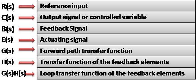
Following figure shows an example of block diagram of a closed loop system. With reference to this figure, the terminology used in block diagram of control system is given below:
Terminology used in block diagram
From the figure it can be clearly seen that the output C(s) is fed back to the summing point where it is compared with the reference input R(s). The output of the block C(s) is obtain by multiplying the transfer function G(s) by the input to the block E(s).
Terminology Used In Closed Loop System
When the output is fed back to the summing point for comparison with the input, it is important to convert the form of the output signal to that of the input, This is done by element H(s). H(s) is known as feedback element. It is generally, a sensor which modifies the output before it is compared with the input. When the output of H(s) that is B(s) is compared with the reference input signal R(s), an actuating error signal E(s) is generated. In the present example the feedback signal that is fed back to the summing point for comparison with the input R(s) is B(s)=H(s)C(s)