Friday, January 18, 2019

Ring Main Unit(RMU) or Ring Main Distribution System

Ring Main  Unit(RMU) is metal enclosed gas insulated compact switchgear unit used in secondary distribution up to 36 kV(36000 Volt), 630A. The RMUs are made of stainless steel and are hermetically tight, welded switchgear vessels. As a result, RMUs are insensitive/less sensitive to uncontrollable environmental conditions such as humidity, dust, condensation, small animals. 
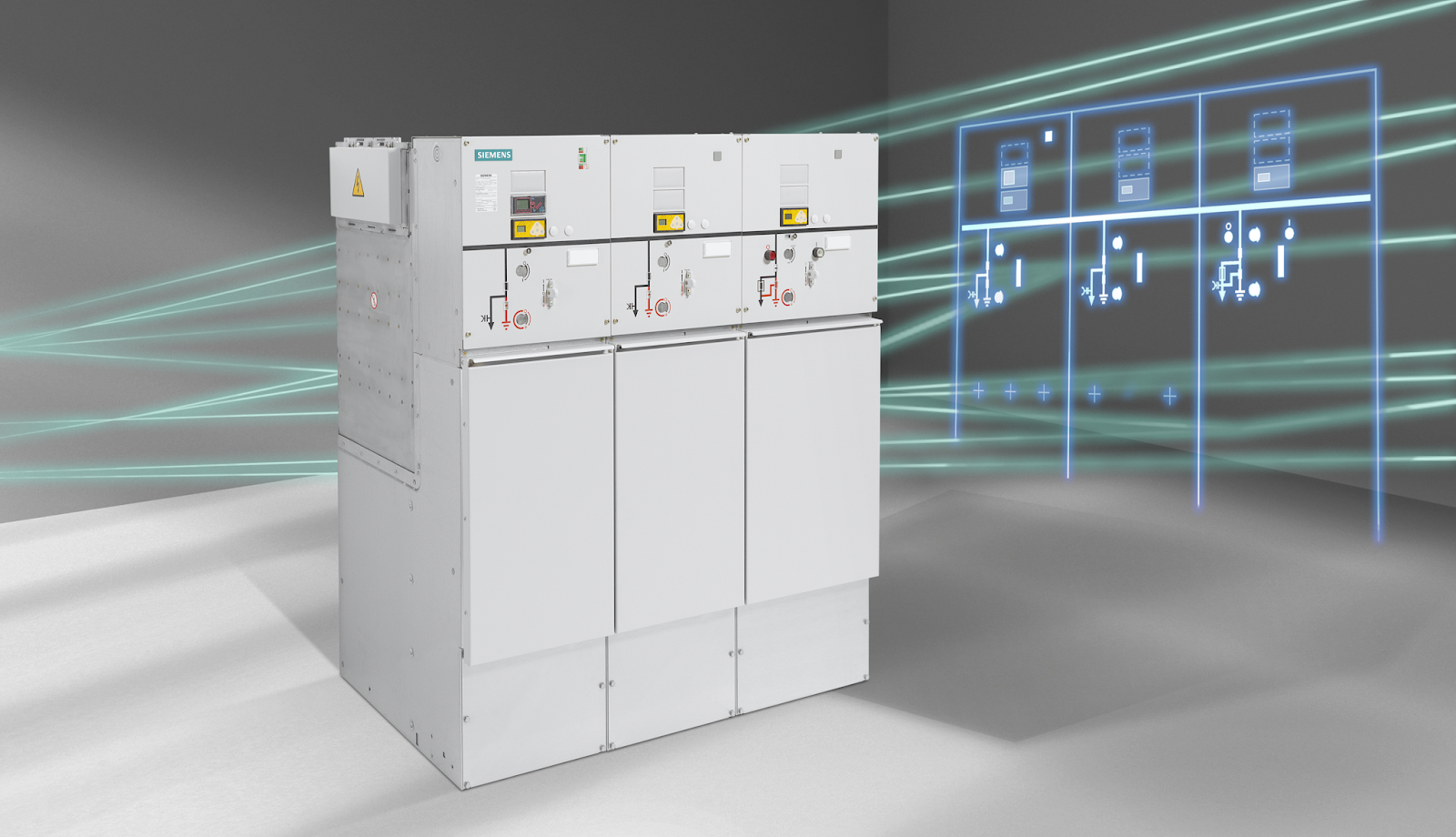
Ring Main Unit - Siemens 8DJH 36
Siemens RMU 8DJH 36

Switchgear vessels designed as sealed pressure systems results in maintenance-free switching devices and thanks to the use of SF6 insulation, compact dimensions are possible.

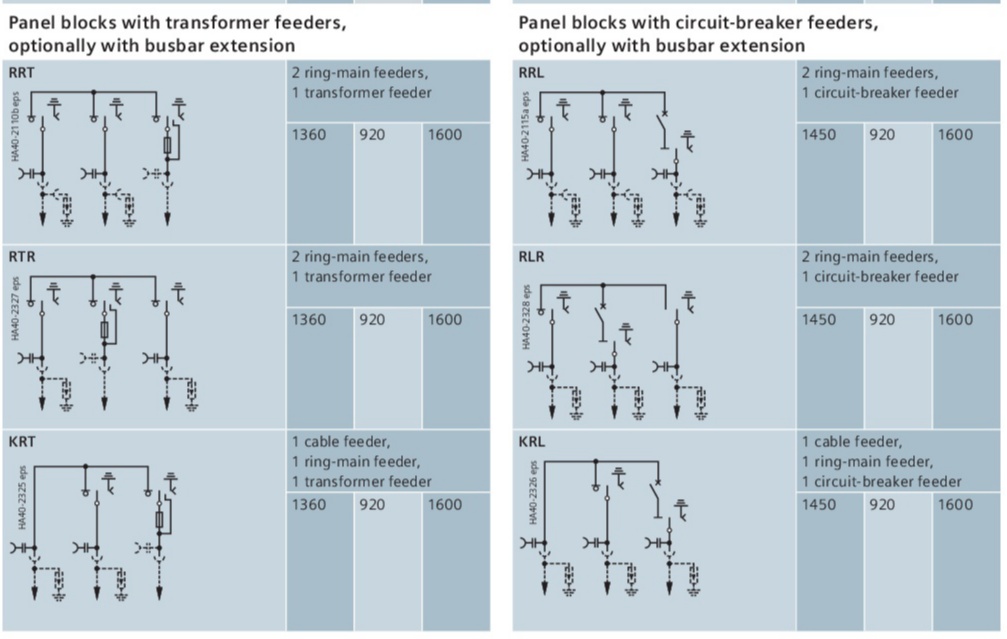
There are different combinations of modules or feeders in an RMU. These modules or feeders provides application of interest. The feeders can be Ring Main feeder, Transformer feeder, Circuit Breaker feeder, Bus Sectionalizer, Cable feeder, billing and metering feeder.
  • Ring main feeder or Ring feeder consist of three position switch(explained later in this article) and current transformers to measure the current incoming from ring. This feeder keeps the individual RMU in ring with larger system of RMUs.
  • Transformer feeder or T feeder consist of Three Position Switch and HRC (high rupturing capacity) fuse to protect the feeder during fault.
  • Circuit Breaker feeder or Line feeder consist of Three Position Switch and Vacuum Circuit Breaker(to disconnect the  system during  fault  condition) and current transformer whose secondary side is connected to a protective relay which sense the fault and give Trip command to the Circuit Breaker at the instant of fault.
  • Cable feeder is vacant individual panel.
  • Billing and metering feeder are used for billing purposes as the name suggests and it consist of Potential transformer (or Voltage transformer).

Three Position Switch

Three position switching devices are of three position design, having the ability to close or open or earth the feeder. To provide better mechanical interlocking, a three position is made of single shafts can be rotated to either closed or opened the disconnector or earth the line (only one operation at any given time).
Three position:-

  1. If the disconnector is closed (line/feeder is live) the switch can never be operated to in earth position. This is known as Service condition.
  2. If the switch is closed in earth position, the switch can never be operated to in disconnector position. This is called Maintenance condition.
  3. The third condition is called neutral or Test. In this condition the switch is closed neither as disconnector nor as earth.
The operation of Three position switch can be fully automated or mechanised. If it is automated it can closed/opened in either disconnector or earth position using a TNC (Trip/Neutral/Close) Switch. If it is mechanised, it can be  operated using an operating lever.

Applications:-

Ring main unit is used in public and industrial energy systems of the secondary distribution level, e.g. in
• Local ring-main units, customer transfer substations and switching substations of power supply and public utilities
• Wind power plants and solar plants, hydroelectric power stations
• Water and liquid waste processing systems
• Airports, train stations, underground stations
• High-rise buildings.

Wednesday, March 23, 2016

Skin Effect in Transmission Lines

The distribution of current throughout the cross section of conductor is uniform only when the steady current(D.C.) is passing through it. However, an alternating current flowing through the conductor does not distribute normally, rather it has the tendency to concentrate near the surface of the conductor as shown in figure below.
Skin effect

What is skin effect

The tendency of alternating current to concentrate near the surface of a conductor is known as skin effect. 
This results in higher resistance to alternating current that to direct current and is more pronounced as frequency is increased. This is known as skin effect. It causes a larger power loss for a given rms ac than the loss when the same value of dc is flowing through the conductor. Consequently, a qualitative explanation of the phenomenon is given below.

" A conductor could be considered as composed of very thin filaments. The inner filaments carrying current gives rise to flux which links the inner filaments only when as the flux due to current carrying outer filaments enclose both the inner as well as the outer filaments. The flux linkages per ampere to inner strands is more as compared to outer strands. The inductance* of each strand will vary according to its position. Thus the strands near the center are surrounded by greater magnetic flux and hence have larger inductance than that near the surface. The high reactance of inner strands causes the alternating current to flow near the surface of conductor. This crowding of current near the conductor surface is the skin effect. "
With the increase of the frequency the non-uniformity of inductive reactance of the filaments becomes more pronounced, so also the non-uniformity of current distribution. For large solid conductors the skin effect is quite significant even at 50Hz. The analytical study of skin effect requires the use of Bessel's functions.
The skin effect depends upon the following factors:-
  1. Nature of material
  2. Diameter of wire- It increases with increase in diameter of wire
  3. Frequency- It increase with increase in frequency.
  4. Shape of wire- It is less for stranded conductor than solid conductor.
It may be noted that skin effect is negligible when the supply frequency is low (≤ 50Hz) and conductor diameter is small (< 1 cm).

Monday, March 21, 2016

Corona phenomenon in Transmission Lines

Corona phenomenon in Transmission Lines
When an alternating potential difference is applied across two conductors whose spacing is large as compared to their diameter, there is no apparent change in the condition of atmospheric air surrounding the conductors, if the applied voltage is low. However when the voltage on line conductor is raised beyond a certain limit, called critical disruptive voltage, the conductors are surrounded by pale violet glow together with a slight hissing noise and a smell of ozone. This phenomena is called as corona.

In short corona phenomena is the ionization of air surrounding the power conductors. Free electrons are normally present in free space because of radioactivity and cosmic rays. As the potential between the conductors is increased, the gradient around the surface of the conductor increases. Assuming that the spacing between the conductors is large as compared with the diameter of the conductors. The free electrons will move with certain velocity depending upon the field strength. These electrons will collide with the molecules of air and in case the speed is large they will dislodge electron from the air thereby the number of electrons will increase. The process of ionization is thus cumulative and ultimately forms an electron avalanche. This results in localization of air surrounding the conductor and hence corona effect is occurred.

Corona occurrence is therefore defined as a self sustained electric discharge in which the filed intensified ionization is localized only over a portion of the distance between the conductors.
The phenomena of corona is accompanied by hissing sound, production of ozone, power loss and radio interference. The higher the voltage is raised, the larger and higher the luminous envelope becomes and greater the sound, the power loss and radio noise. If the applied voltage is increased to breakdown value, a flash over will occur between the conductors due to the breakdown of air insulation.

If the conductors are polished and smoothed, the corona glow will be uniform throughout the length of the conductors, otherwise the rough points will appear brighter. With d.c. voltage, there is difference in the appearance of the two wires. The positive wire has uniform glow about it, while the negative conductor has spotty glow. For a visual corona the line voltage has to be somewhat higher than critical disruptive voltage and is called visual critical voltage.

Friday, July 25, 2014

Power System


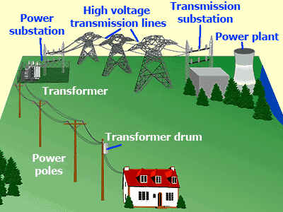
Energy plays a vital role in day to day life of human being for overall development of the country and the world. We know different forms of energy such as wind, solar, thermal, etc. Our dependency on energy is such that without it our life become somewhat cumbersome. For instance, if electricity goes off for a minute we stigmatize the Power Supply Authority.
Electrical Power System- Electicalfreaks.blogspot.in

Electrical Power System 

Electrical Power System- Generation, Transmission, Distribution
Electrical Power System-Generation, Transmission and Distribution
We need to understand that there aren't so much storage of coal, natural gas, so we had to move on Non Conventional Energy Sources e.g. wind, tidal, solar. 
There are various uses of Electrical Energy in different fields such as for domestic purpose, where it is used for heating, cooking, refrigeration, light etc. Also it is used in industries, commercial complexes, irrigation purposes, etc.

To satisfy everyone's need, supply utilities provide electrical energy via a network which is known as Power System. 
Block diagram of Electrical Power System- Electricalfreaks.blogspot.in

As Law of Conservation states, energy can neither be created nor be destroyed, it can be converted from one form to another; power stations converts some of energy into electrical energy.
It mainly consist of two parts, one is turbine and other is alternator for example, turbine converts s\some form of energy into Mechanical form and then alternator converts it into Electrical form. The generated electricity is in the form of 3Ø which is step up in power station. Then it's transmitted to by transmission line over a long distance and then it's stepped down in distribution substation to utilization level. The step up and step down process is done by transformer. 
After that electrical energy is distributed to different consumers.


Meaning of few technical words:-
  • Step Up:- Increasing the magnitude of voltage without change in frequency by transformer.
  • Step Down:- Decreasing the magnitude of voltage without changing its frequency by transfromer