Friday, January 18, 2019

Ring Main Unit(RMU) or Ring Main Distribution System

Ring Main  Unit(RMU) is metal enclosed gas insulated compact switchgear unit used in secondary distribution up to 36 kV(36000 Volt), 630A. The RMUs are made of stainless steel and are hermetically tight, welded switchgear vessels. As a result, RMUs are insensitive/less sensitive to uncontrollable environmental conditions such as humidity, dust, condensation, small animals. 
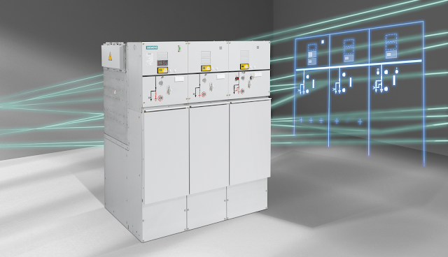
Ring Main Unit - Siemens 8DJH 36
Siemens RMU 8DJH 36

Switchgear vessels designed as sealed pressure systems results in maintenance-free switching devices and thanks to the use of SF6 insulation, compact dimensions are possible.

There are different combinations of modules or feeders in an RMU. These modules or feeders provides application of interest. The feeders can be Ring Main feeder, Transformer feeder, Circuit Breaker feeder, Bus Sectionalizer, Cable feeder, billing and metering feeder.
  • Ring main feeder or Ring feeder consist of three position switch(explained later in this article) and current transformers to measure the current incoming from ring. This feeder keeps the individual RMU in ring with larger system of RMUs.
  • Transformer feeder or T feeder consist of Three Position Switch and HRC (high rupturing capacity) fuse to protect the feeder during fault.
  • Circuit Breaker feeder or Line feeder consist of Three Position Switch and Vacuum Circuit Breaker(to disconnect the  system during  fault  condition) and current transformer whose secondary side is connected to a protective relay which sense the fault and give Trip command to the Circuit Breaker at the instant of fault.
  • Cable feeder is vacant individual panel.
  • Billing and metering feeder are used for billing purposes as the name suggests and it consist of Potential transformer (or Voltage transformer).

Three Position Switch

Three position switching devices are of three position design, having the ability to close or open or earth the feeder. To provide better mechanical interlocking, a three position is made of single shafts can be rotated to either closed or opened the disconnector or earth the line (only one operation at any given time).
Three position:-

  1. If the disconnector is closed (line/feeder is live) the switch can never be operated to in earth position. This is known as Service condition.
  2. If the switch is closed in earth position, the switch can never be operated to in disconnector position. This is called Maintenance condition.
  3. The third condition is called neutral or Test. In this condition the switch is closed neither as disconnector nor as earth.
The operation of Three position switch can be fully automated or mechanised. If it is automated it can closed/opened in either disconnector or earth position using a TNC (Trip/Neutral/Close) Switch. If it is mechanised, it can be  operated using an operating lever.

Applications:-

Ring main unit is used in public and industrial energy systems of the secondary distribution level, e.g. in
• Local ring-main units, customer transfer substations and switching substations of power supply and public utilities
• Wind power plants and solar plants, hydroelectric power stations
• Water and liquid waste processing systems
• Airports, train stations, underground stations
• High-rise buildings.

Sunday, June 25, 2017

Miniature/Low Oil Circuit Breaker

Miniature Oil Circuit Breaker
Photo Credit - ABB Group
In the bulk oil circuit breaker, the oil has to perform two functions, first of all it act as an arc quenching medium and secondly it insulate the live part from earth. It has been found that only small percentage of oil is actually used for arc extinction while the major part is utilized for insulation purposes. For this reason the quantity of oil in bulk oil circuit breaker reaches a very high as the system voltage increases. This not only increases. This not only increases the expenses, tank size and weight of the breaker but it also increases the fire risk and maintenance problems.
A low oil circuit breaker employs solid materials for insulation purposes and uses a small quantity of oil which just sufficient for arc extinction. Regarding quenching the arc, the oil behaves identically in bulk as well as low oil circuit breaker. By using suitable arc control devices the arc extinction can be further facilitated in an low oil circuit breaker.

Construction

Miniature/Low oil circuit breaker
Fig. Miniature/Low oil circuit breaker
Photo Credit - Circuit Globe
Above figure shows the cross section of a single phase low oil circuit breaker. There are two compartment separated from each other but both filled with oil. The upper chamber is the circuit breaking chamber while the lower one is to prevent from mixing with the other chamber. This arrangement permit two advantages. First of all, the circuit breaking chamber requires a small volume of oil which is just enough for arc extinction. Secondly, the amount of oil to be replaced is reduced as the oil in the supporting chamber does not get contaminated by the arc.
  1. Supporting chamber
  2. It is a porcelain chamber mounted on a metal chamber. It is filled with oil which is physically separated from the oil in the circuit breaking chamber. The oil inside the supporting chamber and annular space formed both the porcelain insulation and bakelised paper is employed for insulation purposes only.
  3. Circuit breaking chamber
  4. It is a porcelain enclosure mounted on the top of the supporting compartment. It is filled with oil and has the following parts:-
      Upper and lower fixed contact.
      Moving contact
      Turbulator
    The moving contact is hollow and includes a cylinder which moves down over a fixed piston. The turbulator is an arc control device and has both axial and radial vents. The axial venting ensures the interruption of low currents whereas radial venting vents help in the interruption of heavy current.

  5. Top Chamber
  6. It is metal chamber and is mounted on the circuit breaking chamber. It provides expansion space for the oil in the circuit breaking compartment. The top chamber is also provided with a separator which prevent any loss of oil by centrifugal action caused by circuit breaker operation during fault condition.

Operation

Under normal operating conditions the moving contact remains engaged with the upper fixed contact. When fault occurs the moving contact is pulled down by tripping springs and an arc is struck. The arc energy vaporizes the oil and produces gases under high pressure. This action contains the oil to pass through a central hole in the moving contact and results in forcing series oil oil through the respective passage of turbulation. The process of turbulation is ordinary one in which the section of arc are successively quenched by the effect of separate streams of oil moving across each section in turns and bearing away in gases.

Advantages

  1. It requires lesser quantity of oil.
  2. The space required is small.
  3. There is reduced risk of fire.

Disadvantages

  1. Due to smaller quantity of oil the degree of carbonisation is increased.
  2. There is difficulty of removing the gases from contact space in time.

Wednesday, February 15, 2017

Vacuum Circuit Breaker

Vacuum Circuit Breaker
Image Credit- Siemens Energy
In Vacuum circuit breakers, vacuum (degree of vacuum being in the range 10-7 to 10-5 torr) is used as the arc quenching medium. Since vacuum offers the highest insulating strength it has far superior arc quenching properties than any other medium. For example, when contacts of a breaker are opened in vacuum, the interruption occurs at first current zero with dielectric strength between the contacts building up at a rate thousands of times higher than obtained with other circuit breaker.

Principle:-

The production of a arc in vacuum circuit breaker and its extinction can be explained as follows;-
When the contacts of the breaker are opened in vacuum (10-7 to 10-5 torr), an arc is quickly extinguished because the metallic vapor, electrons and ions produced during arc rapidly condense on the surface of the circuit breaker contacts resulting in quick recovery of dielectric strength. As soon as the arc is produced in vacuum, it is quickly extinguished due to the fast rate of recovery of dielectric strength in vacuum.

Construction:-

Above figure shows the parts of a typical vacuum circuit breaker. It consist of fixed contact and arc shield mounted inside a vacuum chamber. The movable member is connected to the control mechanism by stainless steel bellows. This enables the permanent sealing of the vacuum chamber so as to eliminate the possibility of leak.  A glass vessel or ceramic vessel is used as the outer insulating body. The arc shield prevents the deterioration of the internal dielectric  strength  by preventing metallic vapors falling on the surface of the outer insulating cover.

Working:-

When the breaker operates, the moving contact separates from the fixed contact and an arc is struck between the contacts. The production of arc is quickly extinguished because the metallic vapors, electrons and ions produced during arc are diffused in a short time and seized by the surface of moving and fixed members and shield since vacuum has very fast rate of recovery dielectric strength. The arc extinction in a vacuum breaker occurs with a short contact separation say 0.625 cm.

Advantages:-

  1. They are compact, reliable and have longer life.
  2. There are no fire hazards.
  3. There is no generation of gas during and after operation.
  4. They require little maintenance and arc quiet in operation.
  5. They can successfully withstand lightning surges.
  6. They have low arc energy.


SF6 Circuit Breaker

SF6 Circuit Breaker
SF6 circuit breaker
In such circuit breaker SF6 gas is used as the arc quenching medium. SF6 is an electro-negative gas and has strong tendency to absorb free electrons.The contacts of the breaker are open in the high pressure. Flow of SF6 gas and arc is struck between them. The conducting free electrons in the arc are rapidly captured by the gap to form relatively immobile ions.The loss of conducting electron in the arc quickly builds up enough insulating strength to extinguish the arc. SF6 circuit breaker has been found to be very effective for high power and high voltage service.

Construction:-

Constructional details of SF6 circuit breaker
Above figure shows the parts of typical SF6 circuit breaker. It consists of fixed and moving contacts enclosed in a chamber(called arc interruption chamber) containing SF6 gas. This chamber is connected to SF6 gas reservoir. When the contact of breaker are opened, the valve mechanism permits a high pressure SF6 gas from the reservoir to flow towards the arc interruption chamber. The moving contact is a hollow cylindrical current carrying contact fitted with an arc horn. The moving contact is also a hollow cylinder with rectangular holes in the sides to permit the SF6 gas to let out through these holes after flowing along and across the arc. The tips of the fixed contact and arcing horn are coated with copper-tungsten arc resistant material. Since SF6 gas is costly, it is reconditioned and reclaimed by suitable auxiliary system after each operation of the breaker.

Working:-

In the closed position of the breaker, the contacts remain surrounded by SF6 gas at a pressure of about 2.8 Kg/cm2. When the breaker operates, the moving contact is pulled apart and an arc is struck between the contacts. The movement of the moving contact is synchronized with the operating of a valve which permits SF6 gas at 14 Kg/cm2 pressure from the reservoir to the arc interruption chamber. The high pressure flow of SF6 rapidly absorb the free electrons to form immobile negative ions which are ineffective as charge carriers. The result is that the medium between the contacts quickly build up high dielectric strength and causes the extinction of the arc. After the breaker operation i.e., after arc extinction valve is closed by the action of a set of spring.

Advantages :-

  1. Due to the superior quenching property of SF6 such circuit breaker have very short arcing time.
  2. Since the dielectric strength of SF6 gas is 2 to 3 times that of air, such breakers can interrupt much larger currents.
  3. The SF6 circuit breaker gives noiseless operation due to its closed gas circuit and no exhaust to atmosphere unlike air blast circuit breaker.
  4. The closed gas enclosure keep the interior dry so that there is no moisture problem.

Disadvantages:-

  1. SF6 circuit breaker are costly due to high cost of SF6 gas.
  2. SF6 gas has to be reconditioned after every operation of the breaker. Hence additional equipment is required for this purpose.
There are many advantages of using SF6 circuit breaker, only few have listed above.

Wednesday, June 8, 2016

Classification of Electric Drives

Group Drives

Group Drive
Photo Credit - http://mechaholic.in
It consists of single machine which actuates several machines or mechanism by means of one or more line shaft. Hence this is also called "line shaft drive". This line shafts are connected to multi stepped pulleys and belts that connect this pulley and shaft of the driven machine, serves to vary their speed.

Group drive is economical in consideration for the cost of motor and control gear. A single motor of large capacity costs less than that of the total cost of number of small motors for same total capacity namely, a single motor of 100KW costs less than that of ten motors of 10KW each. Since all the motors may not operate on full load at the same time, the KW rating of motor of group drive is often less than the aggregate KW output rating of the individual motor and further cause reduction in cost.

Individual Drive

Individual Drive
Photo Credit - http://mechaholic.in
In individual drive an electric motor used for transmitting motion to various parts or mechanism belonging to single equipment. For example, such drive are used to rotate the spindle, moves the feed and with the help of gears imparts motion to lubricating and cooling pumps in lathe. In application, individual drive consist of motor which is specifically designed to form an integral part of the machine.

In individual drive, the energy is transmitted to different parts of same mechanism by means of mechanical parts like gear, pulley, etc. hence occurs some power loss.

Multimotor Drive

Multimotor Drive
Photo Credit - http://vertassets.blob.core.windows.net/
The multimotor drive consist of several individual motor which serve to one of many motions or mechanism in some production unit. For example, in travelling crane, there are three motors used. One for hoisting, other for long travel motion and third for cross travel motion. Such a drive is essential in complicated metal cutting machine, paper making machine, rolling mills, rotary printing machine, etc. The use of multimotor drive is expanding in modern industries due to their advantage outweighs increase in capital cost compared to the group drive.

Tuesday, June 7, 2016

Passive Method of Space Heating

Passive method of Space heating
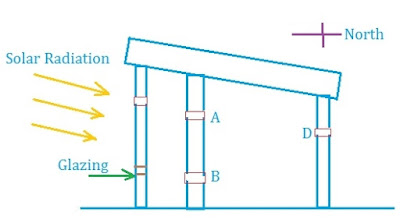
A schematic diagram of passive space heating designed by Professor Trombe is shown in figure. The south face of the house to be heated is provided with single or double glazing. Behind it is a thick black concrete wall which absorbs Sun radiation and serve as thermal storage. Vent A and B which can be opened and closed are provided near the top and bottom of the storage wall. The whole unit consisting of storage wall with vents and glazing is referred as Trombe Wall.

During day time both vents A and B are kept open. The air between inner glazing and wall is heated and flows into living space from top vent. Simultaneously the cool air in the room is pulled out from the living space through bottom vent. Thus a natural circulation path is set up. Some energy transfer in the living space also takes place by convection and radiation from the inner surface of the storage wall. During night energy transfer take place by convection and radiation from the inner surface.

The Trombe Wall can also be used for summer ventilation by providing vent C and D near the top of glazing and north facing wall. On a hot day, vent B, C and D can be kept open while vent A would be kept closed. The heated air between glazing and wall would then flow out through vent C drawing air from the living space to replace it. This in turn would cause air to be pulled in from outside through vent D. Vent D should be located such that air pulled in through it comes from shaded and cool area. 

Solar Water Heater Working (Thermosymphonic Mode)

Solar Water Heater
Solar Water Heater
A Solar Water Heater(SWH) is a device which provides hot water for bathing, washing, cleaning etc. using solar energy. It is generally installed at terrace or where sunlight is available and heats water during day time which is stored in an insulated storage tank for use when required including morning. It basically heats the water using heat energy of the Sun rays. Today we are going to discuss the working of solar water heater in thermosymphonic mode.
Solar Water Heater (Thermosymphonic mode)

A solar water heater is shown in above figure. It consists of a tilted liquid flat plate collector(LFPC) facing south with transparent glass covers, a separate highly insulated water storage tank and well insulated pipes connecting the two. The bottom of the tank is at least 1-2 feet the top of the collector and no auxiliary energy is required to circulate water through it. Circulation occurs through thermosymphonic mode or natural convection. As the water us heated in its passage through the collector its density decreases and hence it rises and flows into the top of the storage tank, colder water from the bottom of the tank has higher density and so tends to sink and enter the lower header of the collector for further heating.
The density differences between the hot water and cold water thus provides the driving force necessary for the circulation of water through the collector and the storage tank, Hot water is drawn off from the top of the tank as required and is replaced by cold water from the service system. As long as the Sun shines the water will quietly circulate getting warmer. To provide heat, during cloudy periods, an electrical immersion heater can be used as backup for the solar system.